Case Study - PostPro3D
Automated Finishing for HP Multi Jet Fusion Technology
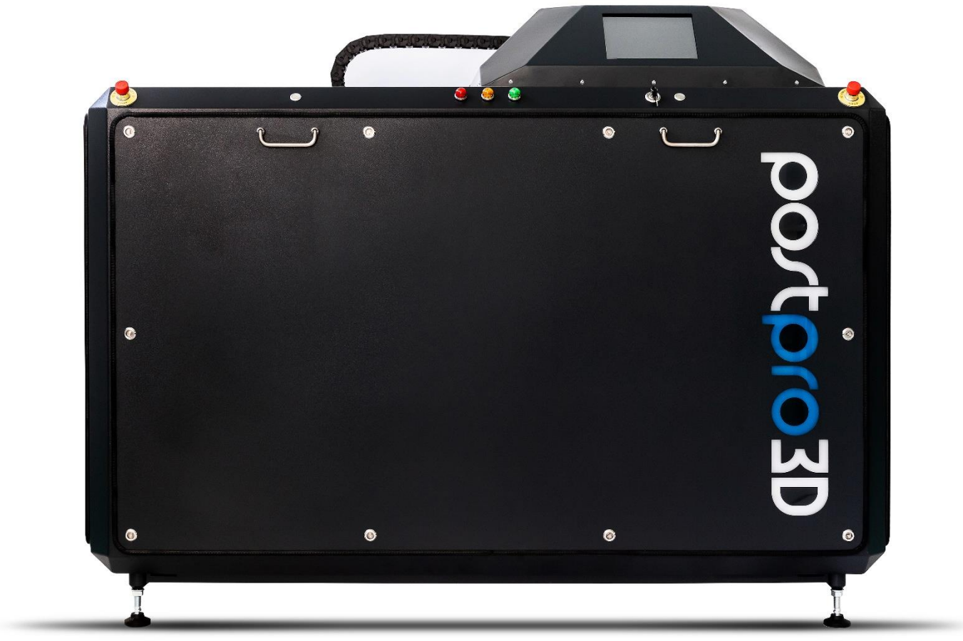
PostPro3D
Additive Manufacturing Technologies (AMT)’s PostPro3D® patent pending technology is a smart and automated post processing solution for thermoplastic polymer 3D Printed parts. PostPro3D® is a CE and UL listed machine and is based on AMT’s proprietary BLAST™ process (Boundary Layer Automated Smoothing Technology).
The BLAST process is a physical-chemical-based process that can smooth a wide variety of thermoplastic polymers. The process is a non-line-of-sight and can smooth complex internal cavities of polymer parts. The PostPro3D technology is highly controllable, allowing reproducible results with no degradation of a parts’ mechanical properties.
The PostPro3D machine is an automated turnkey solution which can be integrated into the digital workflow. Using a series of pre-defined parameter sets and algorithms PostPro3D® achieves for the first time a surface finish that matches injection moulding techniques. This enabling technology reduces lead-time, cost of manufacture, operational and maintenance costs providing the ‘missing piece’ in the digital manufacturing chain.
PostPro3D® makes part surface finishing cost and speed competitive for high volume production.
This white paper details the results of extensive testing carried out on HP’s MJF PA12 material.
Materials
PostPro3D has been designed to process thermoplastic polymer materials. Currently the technology can process Polyamide (Nylon) (6,11,12), Flame retardant Nylons, Carbon/Glass filled derivatives of Nylons, Thermoplastic polyurethane (TPU), and Thermoplastic Elastomers (TPE). This white paper focusses on HP’s Nylon 12 material.
Testing Methodology
Three sets of HP MJF samples each containing three HP calibration pieces (pyramid, heart and plate) were processed to a pre-defined level of surface finish denoted as Finish 1 – Finish 3. Additionally, ASTM D638 TYPE I tensile test samples were processed for the evaluation of surface roughness, dimensional tolerance and mechanical property changes. The samples were printed using a HP MJF 4200 printer and supplied by HP.
Part Preparation
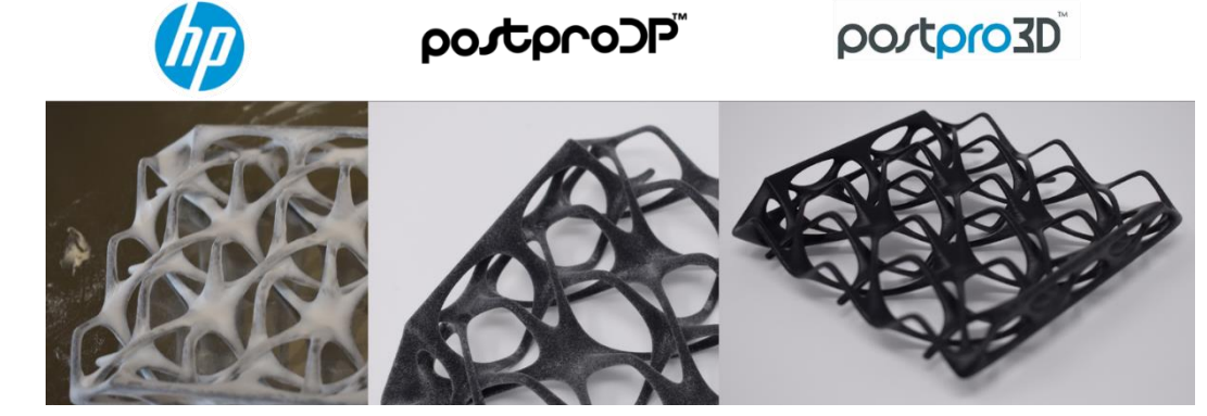
For best results, the parts must be depowered prior to processing with PostPro3D. The following shows the surface conditions of the non-depowdered ‘As Printed’ parts to those after being depowered and then finally after being processed by PostPro3D.
Note: The parts in the picture below were depowdered using AMT’s PostProDP automated depowdering technology.
Printed Part Design Considerations
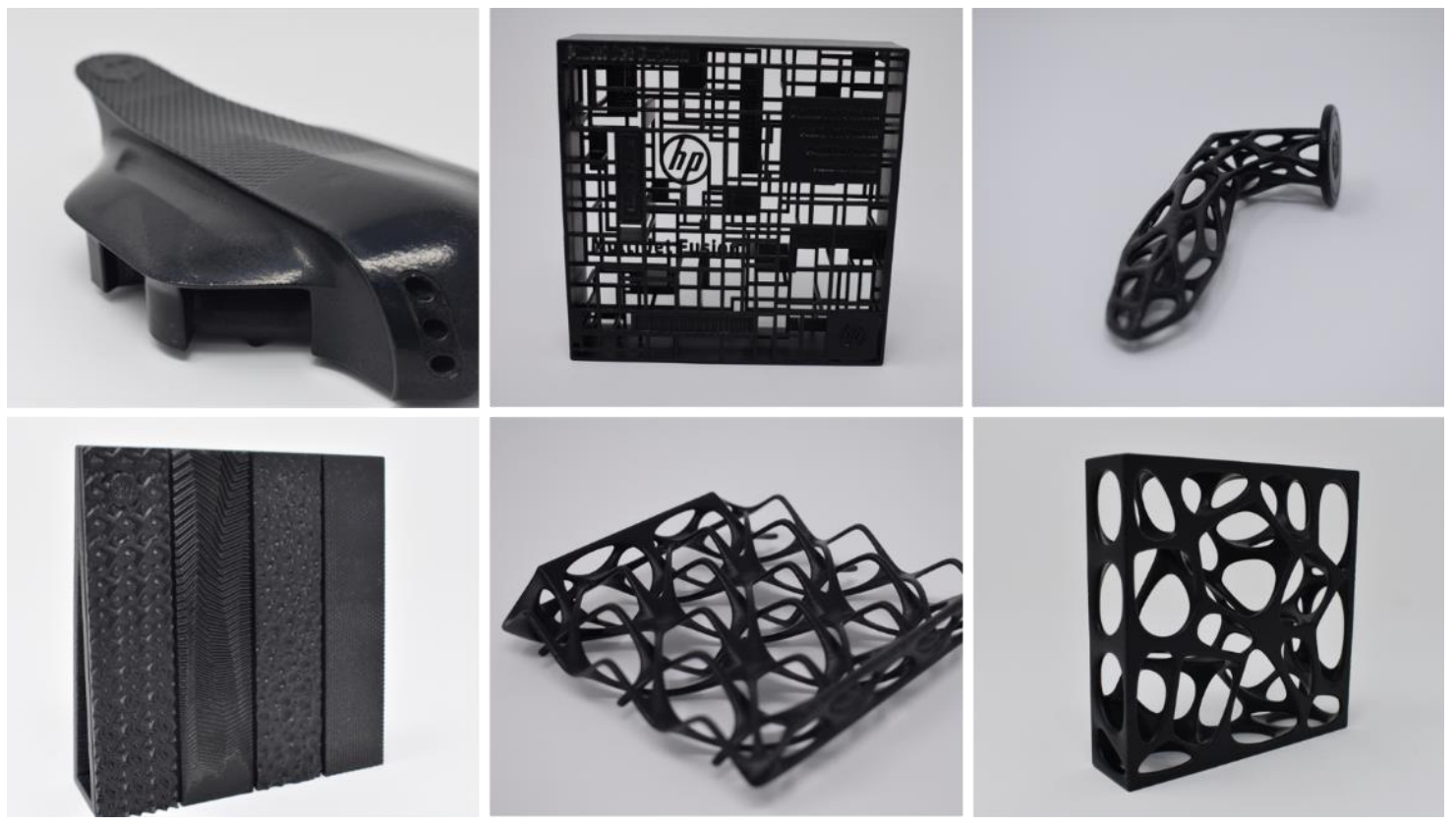
The BLAST process is non-abrasive, as it re-distributes the surface material instead of removing it. Therefore, the process does not damage the delicate structures of the parts. Bores with a diameter as small as 0.3 mm can be smoothed with the BLAST process.
It should be noted that the processing uniformity of MJF parts depends on the thickness of parts’ wall sections. Parts with a significant variation in wall thickness may encounter difficulty during processing. The minimum part thickness that can reliably be processed varies depending on the material and printing conditions. Generally, the recommended part thickness for best processing results is no less than 1 mm.
Improving Surface Roughness
The PostPro3D technology smooths the surface of a polymer part using a program with a selection of a predefined set of parameters. Each set of samples was processed in separate batch using a different parameter set. Each complete process run took 1 hour.
The surface roughness of the samples was measured using Mitutoyo Surftest SJ-210 surface roughness measurement device with the stylus tip radius of 2μm, tip angle 60° and measuring force 0.75kN. Five measurements at different areas of each surface were made before and after processing and the average taken. This was performed in accordance with ASTM standard ASTM D7127. The three standard surface finishes are compared to un-processed (as-printed) surfaces as shown below. Note the repeatability of the smoothed surfaces is demonstrated by the small standard deviation.

Mechanical properties
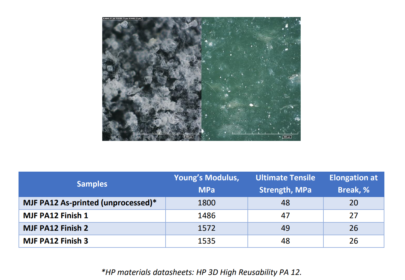
Ultimate tensile strength, elongation at break and Young’s modulus were measured for the processed and un-processed PA 12 samples. Samples were prepared to ASTM D638 Type 1 dimensions. The gauge length of the tensile testing machine was 50mm and tested at a speed of 5mm/min.
The results show no loss in Ultimate Tensile Strength in processed samples. Elongation at Break (EAB) of the tested samples has significantly increased, whereas the Young’s Modulus decreased. The increase in EAB can be explaining by the reduction of crack initiation sites on the polymer surface due to the removal of surface porosity, as shown in the microscopy image below. The results are summarized in the table below:
Dimensional Variation
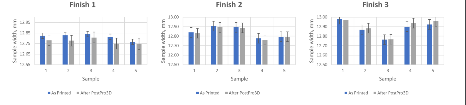
Parts processed in the PostPro3D machine exhibit no more than 0.4%-dimensional change irrespective of desired finish level. This negligible dimensional variation results in the retention of part tolerances and retention of fine feature details. Note there is no trend in variation of each finish, i.e. Finish 3 does not necessarily make parts thicker/thinner than Finish 1.
Part Colouring
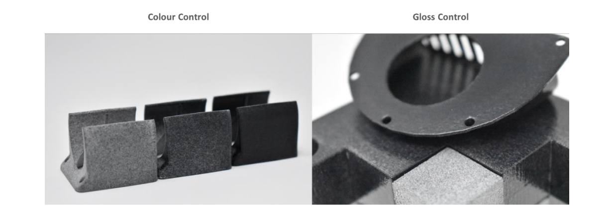
During the BLAST process, the surface of the material is redistributed in a controlled manner. This enables various surface effects to be achieved on the part, including different black colour saturation and level of gloss. The colour can be controlled from grey to piano black. This important effect allows for the first time HP MJF parts to achieve a ‘dyed-like’ and smoothed surface in one process.
Water Absorption
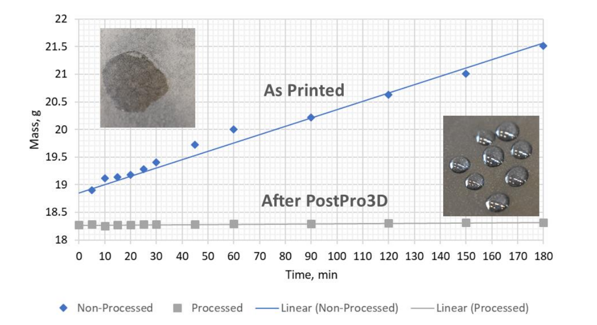
Water immersion experiments on the samples were completed to investigate the effectiveness of the process to protect the surface of the material from water absorption. Processed and non-processed samples with the surface area of 208 cm2 were immersed in water and the weight of the samples was logged with time. Water tends to ‘stick’ to the surfaces of unprocessed samples, which results in higher weight increase for the parts with high surface area. On the other hand, the water is deflected from the surface of the processed samples. The reason for water protective properties is low surface energy of the processed material, which in turn results in high contact angle between the processed surface and water.
Cytotoxicity
The cytotoxicity test is one of the biological evaluations and screening tests that use tissue cells in vitro to observe the cell growth, reproduction and morphological effects by medical devices. Cytotoxicity is an important indicator for toxicity evaluation of medical devices as it is simple, fast and has a high sensitivity.
Cytotoxicty tests were carried out at a nationally recognized European laboratory to Normative References: ISO 10993-5 (2009); ISO 10993-1 (2010); ISO 10993-12 (2012).
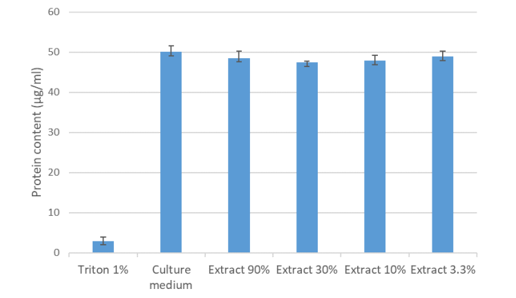
The results show that in the presence of Triton X 100 in the cell culture medium, 6.0 % of the protein content compared to the negative control was reached. This value is within the valid range of 15 % protein content or less compared to the negative control. Materials are considered cytotoxic, if the material extract leads to a protein content of the test cells of less than 70 % compared to the negative control.
This was not the case in this test. The material extract therefore does not show a cytotoxic effect.